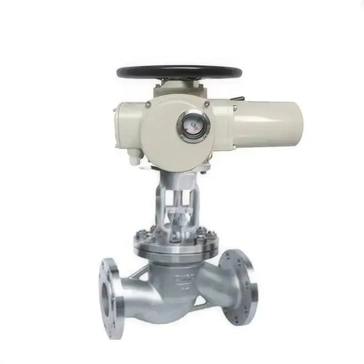
Control valves are among the most essential components in modern industrial automation and process engineering systems. They serve as the final control element in a process loop, responsible for regulating flow rate, pressure, temperature, and liquid or gas levels. Across industries such as oil and gas, petrochemicals, power generation, metallurgy, pharmaceuticals, and water treatment, control valves play a decisive role in ensuring process stability, safety, and efficiency.
As industrial systems become increasingly complex and automated, the performance requirements for control valves continue to rise. Engineers are no longer concerned only with basic opening and closing functions; instead, they demand high precision, stable modulation, low energy consumption, and long service life under harsh conditions.
Among all performance parameters, flow capacity stands out as one of the most critical. It directly determines how much fluid a valve can pass under specific conditions and significantly influences the overall performance of the control system.
This article provides a comprehensive analysis of control valve structure, classification, flow behavior, flow coefficient theory, performance characteristics, and practical selection principles, offering a complete understanding of how modern control valves operate in real industrial environments.
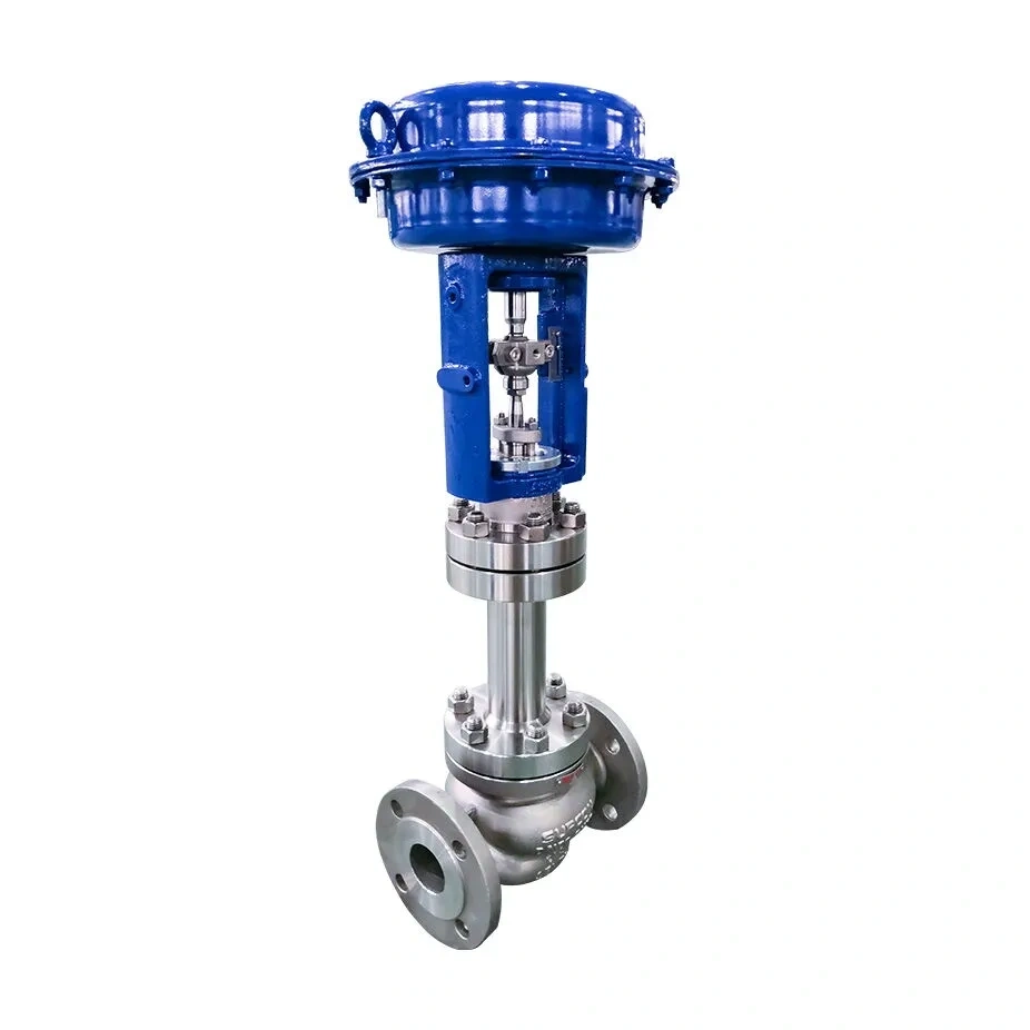
A control valve is generally composed of two primary subsystems: the actuator and the valve body.
The actuator is responsible for converting control signals into mechanical motion. It receives signals from distributed control systems (DCS), programmable logic controllers (PLC), or other automation platforms and adjusts the valve opening accordingly.
There are two major types of actuators:
- Pneumatic actuators
- Electric actuators
Pneumatic actuators are widely used due to their fast response time, simple design, and high reliability in hazardous environments. They are particularly common in oil, gas, and chemical industries where safety is a priority.
Electric actuators, on the other hand, offer high positioning accuracy and are suitable for applications requiring remote control, digital integration, and precise modulation.
The valve body is the main pressure-bearing structure and determines how the fluid flows through the system. It contains internal components such as the plug, seat, cage, or disc depending on valve type.
The geometry of the valve body directly affects:
- Flow capacity
- Pressure drop
- Sealing performance
- Flow characteristics
Even minor differences in internal structure can significantly influence performance under varying operating conditions.
Control valves can be broadly classified based on their motion type into linear motion valves and rotary motion valves. Each category has unique structural characteristics and application advantages.
Linear motion control valves regulate flow by moving a plug or stem in a straight vertical direction.
Single-Seat Control Valves
Single-seat valves are widely used in applications requiring tight shut-off performance. Their structure consists of one seat and one plug, forming a single sealing surface.
Advantages:
- Excellent sealing performance
- Simple structure
- High precision in small flow control
Limitations:
- Limited flow capacity
- High unbalanced force
Not suitable for large-diameter or high-flow applications
Single-seat valves are commonly used in chemical dosing, laboratory systems, and precision process control applications where leakage must be minimized.
Double-Seat Control Valves
Double-seat valves feature two sealing surfaces, which balance the forces acting on the valve plug.
Advantages:
- High flow capacity
- Reduced unbalanced force
- Stable operation under high-pressure conditions
Limitations:
- Slightly lower sealing performance compared to single-seat valves
- More complex internal structure
Double-seat valves are widely used in large industrial pipelines where flow volume is high and minor leakage is acceptable.
Rotary motion valves regulate flow by rotating a closure element such as a ball or disc. These valves are known for compact design and fast operation.
V-Port Ball Control Valves
V-port ball valves feature a V-shaped notch in the ball. This design enables precise throttling and stable flow control.
They are commonly used in:
- Slurry systems
- Chemical processing
- Fibrous media handling
Pneumatic Diaphragm Valves
These valves use a flexible diaphragm to control flow. The diaphragm moves up and down in response to pneumatic pressure.
Advantages:
- Excellent sealing performance
- Suitable for corrosive and sanitary applications
- Simple maintenance
They are widely used in pharmaceutical, food, and biotechnology industries.
Eccentric Butterfly Valves
Eccentric butterfly valves use an offset disc design to reduce friction during operation. This improves sealing performance and extends service life.
They are suitable for:
- Large-diameter pipelines
- Water treatment systems
- HVAC systems
Flow capacity is closely related to how fluid behaves inside the valve. Understanding fluid dynamics is essential for accurate valve design and selection.
At low flow rates, especially in viscous fluids, the flow is typically laminar. In this state:
- Fluid moves in parallel layers
- Minimal mixing occurs
- Flow rate is proportional to pressure difference
This condition is stable but limited in energy transfer.
As flow increases, the system enters a transitional phase where laminar and turbulent flow coexist. In this region:
- Flow becomes unstable
- Pressure-flow relationship becomes nonlinear
- Predictability decreases
- Turbulent Flow Regime
At high flow rates, fluid becomes fully turbulent:
- Flow is chaotic and energetic
- Strong mixing occurs
- Flow is less sensitive to viscosity
However, most low-flow control valves never reach fully turbulent conditions, making traditional models less accurate in such cases.
The Reynolds number is used to describe flow behavior. It determines whether the flow is laminar, transitional, or turbulent.
Flow capacity directly influences multiple performance characteristics of a control valve.
Higher flow capacity allows smoother modulation across operating ranges, improving control accuracy.
The turndown ratio represents the controllable flow range:
Turndown Ratio = Qmin / Qmax
A higher ratio means better flexibility in flow control. Industrial systems typically require a ratio between 10:1 and 15:1.
Improper flow capacity selection can lead to:
- Oscillations
- Pressure fluctuations
- Poor regulation response
In real pipeline systems, resistance changes can distort valve characteristics:
- Linear characteristics may behave like quick-opening curves
- Equal-percentage curves may become linear
This is especially noticeable in high-pressure systems with multiple valves in series.
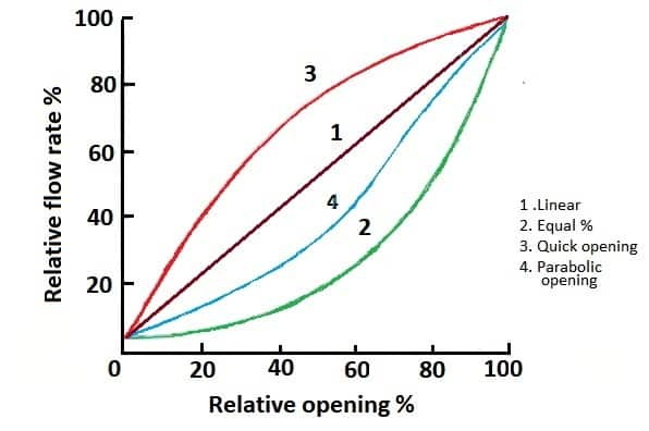
The flow coefficient defines the capacity of a valve to pass fluid under standardized conditions.
Cv and Kv Definitions
Two international standards are widely used:
- Cv (ISA standard)
- Kv (IEC standard)
Their relationship is:
Cv≈1.167Kv
Cv Definition
Cv represents the flow of water (60°F) in gallons per minute through a valve with a pressure drop of 1 psi.
Kv Definition
Kv represents the flow of water (5–40°C) in cubic meters per hour under a pressure drop of 1 bar.
Calculation Complexity
Flow coefficient calculation involves:
- Fluid density
- Viscosity
- Compressibility
- Pressure differential
- Choking conditions
Due to complexity, modern industries rely on simulation software to improve accuracy and efficiency.
Low-flow valves are used in highly precise applications such as:
- Chemical dosing
- Laboratory systems
- Instrumentation pipelines
Key Challenges
- Extremely small flow range
- High sensitivity requirements
- Leakage control difficulties
Even when fully closed, micro-leakage can affect system accuracy.
International standards strictly regulate leakage rates, ensuring safety and reliability even at extremely low Cv values.
Selecting the correct control valve requires systematic engineering evaluation.
- Viscosity
- Density
- Corrosiveness
- Phase (gas/liquid/steam)
- Temperature range
- Pressure range
- Flow variability
- Upstream/downstream resistance
- Installation orientation
- Space constraints
- Accuracy level
- Response speed
- Stability requirements
- Initial cost
- Maintenance cost
- Lifecycle performance
- Industrial Applications
Control valves are used across nearly all industrial sectors:
- Oil refining and transportation
- Natural gas distribution
- Power plant steam systems
- Chemical manufacturing
- Water treatment and desalination
- Pharmaceutical production
- Food and beverage processing
Each application requires specific valve characteristics tailored to process needs.
Modern control valve technology is evolving rapidly.
Smart Control Integration
Digital actuators and IoT connectivity allow:
- Remote monitoring
- Predictive maintenance
- Real-time diagnostics
- Advanced Materials
New materials improve performance in extreme conditions:
- High-temperature alloys
- Corrosion-resistant coatings
- Ceramic sealing surfaces
- Simulation-Based Design
CFD (Computational Fluid Dynamics) is increasingly used to:
- Optimize internal flow paths
- Reduce turbulence
- Improve efficiency
- Energy Efficiency Optimization
Modern valves are designed to reduce:
- Pressure loss
- Energy consumption
- Operational waste
Control valves are fundamental to modern industrial systems, and their performance directly affects process efficiency, safety, and operational stability. Among all performance parameters, flow capacity remains the most critical factor in determining valve suitability.
A deep understanding of valve structure, fluid behavior, flow coefficient theory, and system interaction is essential for correct selection and optimization. As industrial automation continues to advance, control valves are becoming more intelligent, precise, and adaptable to increasingly complex environments.
Future developments will continue to focus on smart integration, advanced materials, and high-precision flow control, ensuring that control valves remain at the heart of industrial process engineering worldwide.